Internet Toolset Blog
Unified Modeling Language (UML): A Guide to Software Architecture Modeling
Unified Modeling Language (UML) is a standardized specification language used to visualize, construct, and document the design of software-intensive systems. It provides a universally understood set of notations for describing a system’s structural and behavioral characteristics. Originally standardized by the Object Management Group (OMG), UML serves as the de facto language for object-oriented analysis and design in enterprise, embedded, and web-scale software systems.
1. Introduction to UML
UML is a general-purpose modeling language, not a programming language. It does not include implementation semantics; rather, it is designed to express conceptual and logical designs. The primary use of UML is in software engineering and systems design, though it is also used in business modeling and process documentation. Its goal is to unify previously fragmented diagramming methods into a consistent notation that spans multiple domains and levels of abstraction.
Since its formal adoption in 1997, UML has undergone numerous revisions. The most widely adopted version is UML 2.5, which includes updates to semantics, notation, and tool compliance. The UML 2.x architecture is divided into four layers: the user model, the UML model, the metamodel, and the meta-metamodel (MOF).
2. The Four-Layer Metamodel Architecture
The UML specification defines a four-layered architecture that supports modeling languages as model-driven systems:
- M0 – User Level: The actual system being modeled.
- M1 – Model Level: The UML diagrams representing the system.
- M2 – Metamodel Level: The UML language constructs (classes, associations, etc.).
- M3 – Meta-metamodel Level: The Meta-Object Facility (MOF), which defines the rules for creating metamodels.
This architecture provides semantic rigor and extensibility to UML. It enables the definition of modeling languages and tool interchange standards (e.g., XMI – XML Metadata Interchange).
3. Structural vs. Behavioral Diagrams
UML divides its diagram types into two primary categories: structural and behavioral. Structural diagrams depict the static aspects of a system—its components, relationships, and topology. Behavioral diagrams illustrate system dynamics, interactions, workflows, and state changes over time.
4. Overview of UML Diagram Types
UML 2.5 defines 14 standard diagram types, grouped into structure and behavior categories. Each diagram has a specific purpose and notation style. Here is a concise technical summary of each.
Structural Diagrams
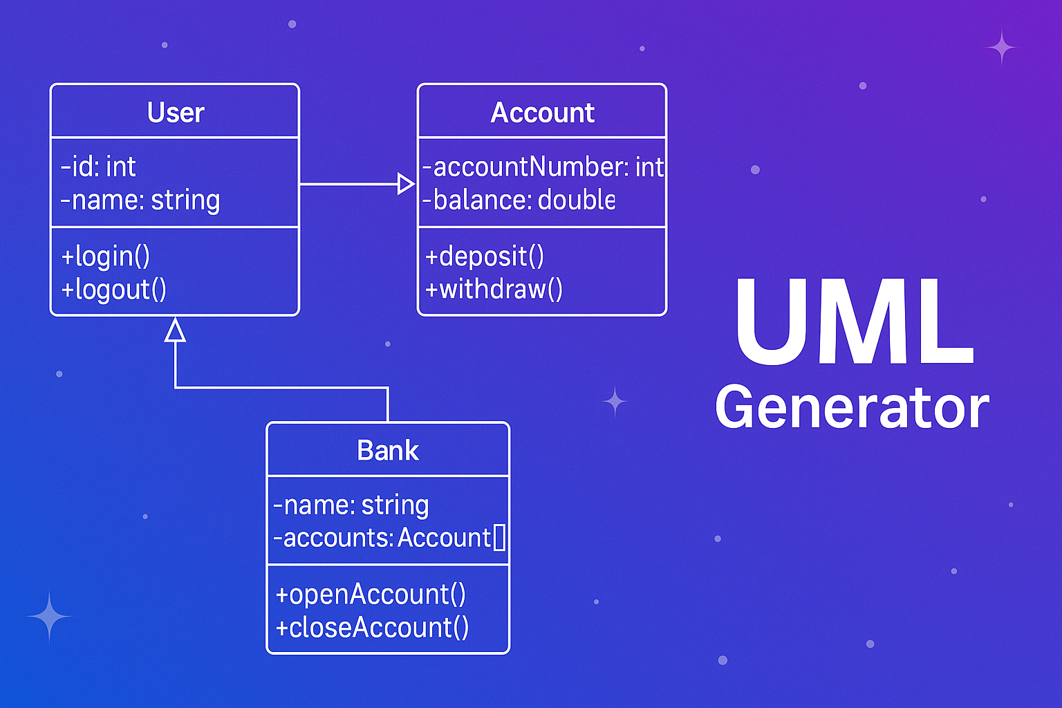
- Class Diagram: Describes the system’s classes, attributes, operations, and relationships.
- Object Diagram: Represents instance snapshots of classes at runtime.
- Component Diagram: Shows physical components and their interdependencies.
- Deployment Diagram: Details hardware nodes and deployed artifacts.
- Package Diagram: Depicts logical containers and their relationships.
- Composite Structure Diagram: Illustrates internal structures and role-based collaboration.
- Profile Diagram: Customizes UML metaclasses for specific domains.
Behavioral Diagrams
- Use Case Diagram: Displays actors and system use cases.
- Activity Diagram: Shows business process and logic flow.
- State Machine Diagram: Represents lifecycle of objects and states.
- Sequence Diagram: Describes interaction order between lifelines.
- Communication Diagram: Focuses on links and message flows.
- Timing Diagram: Analyzes timing constraints among interactions.
- Interaction Overview Diagram: Combines activity and sequence elements.
5. Practical Examples of UML in Use
To illustrate UML usage, consider a retail ecommerce application. A class diagram may define entities such as Customer, Product, Order, and Inventory. Sequence diagrams map operations like checkout or order confirmation, while activity diagrams model the fulfillment workflow from purchase to shipment.
In microservices environments, component diagrams show service boundaries and APIs, and deployment diagrams specify cloud infrastructure layers including containers, virtual machines, and databases.
6. Integrating UML into Development Workflows
Modern SDLC processes like Agile and DevOps emphasize rapid iteration and continuous integration. UML can support these paradigms when used judiciously:
- Lightweight UML for sprint-level planning and design spikes
- UML diagrams in architecture review boards
- Sequence and class diagrams embedded in markdown specs
- Reverse-engineered class diagrams for legacy refactoring
7. Automation and Code Integration
UML supports Model Driven Architecture (MDA), in which platform-independent models (PIM) are transformed into platform-specific models (PSM) and ultimately into code. Automation tools facilitate:
- Generating Java, C++, Python, or C# code from UML class models
- Parsing source code to regenerate class and package diagrams
- Maintaining synchronization between diagrams and codebases
PlantUML, StarUML, Visual Paradigm, and web-based services such as the UML Generator provide visual and textual workflows for generating diagrams from typed source structures.
Related Articles


Recommended Next Actions
Build File Type Policy
Generate practical allow/deny policy rules for uploads.
Create File PolicyValidate File Types
Test extension and MIME handling before deployment.
Validate Files